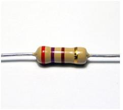
What is Resistor?
A resistor is a device in which electricity cannot pass through it easily. When certain amount electricity is allowed to pass through a resistor, the electrical energy is changed into another form. The other form of energy is usually light or heat. The working principle of bulb is that electricity is passed through the filament usually tungsten, which is a resistor. The energy is converted to and released as light and heat.
The resistor is an electrical component which creates a resistance in the flow of electric current.
A resistor is a basic electrical component found in almost all electronic circuits and electrical networks. A resistor is two terminal passive electrical component. It is a passive component as it consumes energy from a source (active component).
Although resistors are generally used to reduce the flow of current or lower the levels of voltage in a circuit, they are used in many electronic circuits for many purposes. Some of them are the basic current flow limitation ability, to provide a biasing condition to some of the active elements like transistors or to act as a terminating device in transmission lines.
Practically resistors are discrete components of various forms but are also implemented on integrated circuits.
Back to List
Resistor Symbols
Generally there are two standards that are used to denote the symbol of a resistor viz. Institute of Electrical and Electronics Engineers (IEEE) and International Electro Technical Commissions (IEC).
The IEEE symbol of resistor is a zigzag line as shown in the below figure.

Resistor Symbol
The IEC symbol for resistor is shown below.
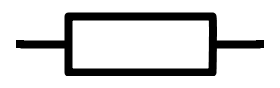
Resistor IEC Symbol
There are some other symbols of resistors in use , based on the type. Each type has both IEEE symbol and IEC symbol. The types of resistors are potentiometer and variable resistor which is generally known as rheostat.
The IEEE symbol for potentiometer is shown below.

Potentiometer Symbol
The IEC symbol for potentiometer is

IEC Symbol for Potentiometer
The IEEE symbol for rheostat is

Rheostat Symbol
The IEC symbol for rheostat is

Rheostat IEC Symbol
Resistance
The mechanism of energy flow through a conductor can be described as follows: In the presence of an active source, the passive elements like resistors will always absorb energy and the currents through them will always flow from higher potential to lower potential.
If we apply the same potential difference between the ends of two different but geometrically similar conductors like rods of copper and of glass, it results in different currents. This characteristic of the conductor that results in different currents is its electrical resistance.
The definition of resistance can be derived from the Ohm’s law in its Electromagnetic theory form or Continuum form:
J = σ E ---- 1
Here σ is the conductivity of the material i.e. conductor.
E is the electric field developed along the length of conductor due to flow of electrical energy through the conductor.
If ‘V’ is the voltage drop across the conductor and ‘L’ is the physical length of conductor then
E = V/L -------------- 2
The current density J is resulted within the conductor due to the flow of electrical energy through the conductor.
If ‘I’ is the current flowing through the conductor and ‘A’ is the cross sectional area of conductor, then by the definition of current density
J = I/A ----------------- 3
Now combining equations 1, 2 and 3
I/A = σ V/L
=> V = (L/Aσ)I ---------------- 4
The term in parenthesis is constant and let us denotes it by ‘R’.
∴ V = R I
This is the Ohm’s law form in circuit analysis.
By the definition of Ohm’s law, the current flowing through a conductor is directly proportional to the potential difference applied.
I ∝ V
The proportional constant is called Resistance parameter of the conductor R.
∴ I = V/R
R = V/I
The resistance of a conductor, between its two points is determined, by applying a potential difference V between those two points and measuring the current I .
The unit of resistance is Volts per Ampere and is given the name Ohm (Ω).
∴ 1Ω = 1 volt per ampere = 1 V/A.
From earlier calculations,
V = (L/Aσ) I
∴ R = (L/Aσ)I
σ is the conductivity of the conductor which is the measure of conductor’s ability to conduct electric current.
1/σ is the reciprocal of electrical conductivity called electrical resistivity denoted by the symbol ρ (rho).
Resistivity is the measure of a conductor’s ability to resist the flow of electric current.
∴ Resistance of a material ∝ resistivity of the material.
R = (ρL/A) Ω
Resistance of a conductor can be defined as the conductor’s opposition to the flow of current through it.
Resistance is a property of an object like conductor. Resistivity is a property of a material from which the object is made.
The definition of resistor can be written as:
A conductor whose function is to provide a specified resistance in a circuit.
Be Continued,,,,
...
..
.